In-Tank Shaft Configuration

Home

>

Knowledge

>

In-Tank Shaft Configuration

571 views

In-Tank Shaft Configuration

In-Tank Shaft Configuration
The shaft configuration selected for a specific mixer application depend on the process requirements such as 'the tank geometry', 'the drive unit', and 'economics'. The selection usually requires analyzing more than one design. However, the final selection must also meet the drive limitations.

The way of the shaft is supported and coupled to the drive is an important consideration. There support and coupling determine the force and moment transfer between the drive and the in-tank shaft. These force and moment affect the bearing service life. the drive gear bearing, and housing deflections. Most manufacturers publish overhung load limitation for the output shaft of their drive.

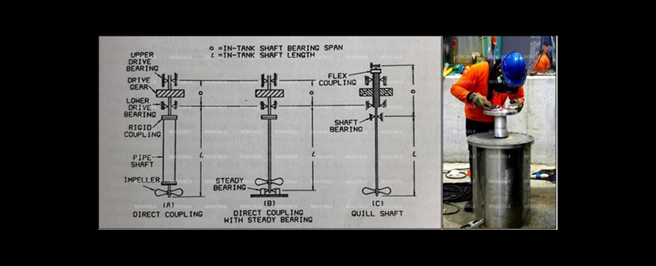
The illustrates different shaft supporting and coupling methods for three in-tank shaft configurations for top entry agitators, The direct coupled shaft (Fig-A) is supported by drive bearing and is drive by the the drive output gear. In this arrangement, the lower shaft is designed to carry only the impeller loads, and the upper portion is designed to carry both the impeller loads and the gearing reactions. Consequently, the load-carry capacity of the lower shaft is limited by the capacity of the upper drive shaft.

The direct-coupled shaft with steady bearing (Fig-B) used for very long shafts which exceed either the shaft limitations of the drive or the critical speed limitations. The steady bearing reduces the drive reaction and gearing deflections. This reduction generally places the bending moment created by the impeller within the shaft limitations of the drive.

In Fig-C, the quill shaft configuration has two shafts connected by a flexible coupling which primarily transmit torque. This arrangement isolates the drive shaft from the bending moments and thrust of the agitator shaft. The agitator shaft has two independent bearings which are usually mounted on the top and bottom of the drive housing. This top and bottom arrangement has a larger bearing span than that of the direct-coupled shaft. Larger bearing span give smaller bearing reactions for the same overhung loads.

ในส่วนของมาตรฐานการออกแบบของบริษัทฯ
1. เลือกใช้ Solid Shaft เป็นอันดับแรกหากไม่ถูกจำกัดโดยงบประมาณของลูกค้า
2. หากใช้ Hollow Shaft ต้องใช้ Steady Bearing เท่านั้น
3. เพลายาวไม่เกิน 2.5 เมตร อาจจะ ไม่ต้องใช้ Steady Bearing
4. เพลายาวเกิน 3.0 เมตร ต้องใช้ Steady Bearing
5. เพลายาวเกิน 9.0 เมตร ต้องใช้ Steady Bearing 2 Stages

ขอบคุณครับ
สถาพร เลี้ยงศิริกูล (Agitator Designer)
MISCIBLE TECHNOLOGY CO., LTD
Tel: 02.548.0414-5 / 091.7400.555
Line : @agitator
www.miscible.co.th


Blogs

-

How to Calculate Mixing Time. By MISCIBLE..(1)

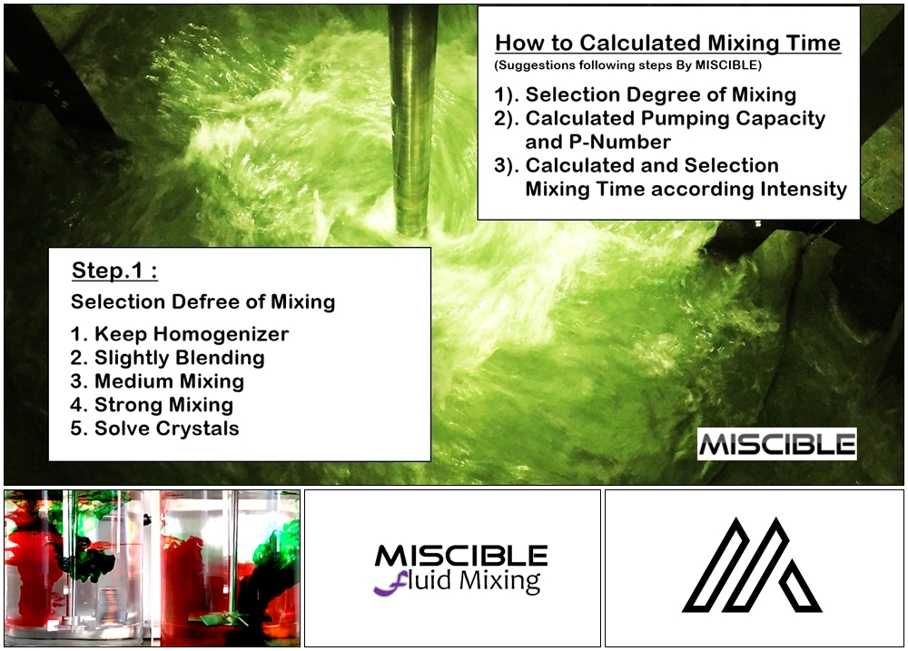
How to Calculate Mixing Time. ? By MISCIBLE เราจะคำนวณและประมาณ Mixing Time อย่างไรให้ใช้งานได้จริงๆ Step-1 : Selection Degree of Mixing ก่อนอื่นต้องขอบอกว่าคำว่า Mixing Time ในนิยามนี้คือ เวลาที่ผสมแล้วเสร็จนะครับ ไม่ได้อ้างอิง Blending, Suspension, Dispersion ฯลฯ เพราะเวลาที่ใช้ผสมเสร็จแต่ละกระบวนการก็เรียกต่างกัน แต่เอาเป็นว่าอย่าทำเรื่องง่ายเป็นเรื่องยาก ก็ใช้คำว่า Mixing Time ก็จบครับ เข้าใจกันง่ายๆดี เราจะไม่หา Mixing Time แบบการใช้ Scale Up นะครับ เพราะถ้าทำแบบนั้น เราคงต้องทำ Existing Model ในแล๊ปกันตลอด ซึ่งในชีวิตจริงไม่มีใครทำกันครับ (เว้นแต่มันจำเป็นจริงๆ) หรือ หากจะศึกษาการหา Mixing Time โดยการใช้ Scale Up ก็สามารถหาอ่านได้ทั่วไปครับมีข้อมูลเยอะมากๆให้อ่านกัน, แต่เราจะพูดกันถึงในจุดที่ว่า...เราคือผู้ออกแบบและผลิต และ กรณีที่เราต้องสร้าง Mixing Tank ขนาด 5,000 ลิตร, แล้วเราจะต้องรับประกัน Mixing Time กับลูกค้า...แล้วเราจะทำอย่างไร...? Step-1 : Selection Degree of Mixing อ้างอิงการออกแบบตามแนวทางของ MISCIBLE, ผมจะแบ่ง Degree of Mixing ออกเป็น 5 ประเภท คือ 1. Keep Homogenizer 2. Slightly Blending 3. Medium Mixing 4. Strong Mixing 5. Solve Crystals ขั้นตอนในการเลือก Degree of Mixing จะเลือกหลังจากเราได้ออกแบบและคำนวณ Speed of Impellers เรียบร้อยแล้วครับ, จากนั้นเราจะมาเลือก Degree of Mixing ให้เหมาะกับ Mixing Task, ตรงนี้พูดตรงๆคือ ต้องอาศัยประสบการณ์จริงๆครับ ไม่มีตำราสรุปให้เป็นแน่เพราะงาน Mixing มันกว้างมากๆ มาดูวิธีการกันครับ Vessel Diameter : 2000 mm Liquid Level : 1591.55 mm Volume : 5000 Liters ขั้นตอนแรก : Volume Calculation ก็ทำตามปกติครับ ให้ได้ Working Volume ออกมาตามที่กระบวนการต้องการ, ตรงนี้จะใช้ Dimension ความยาวเฉพาะ เส้นผ่านศูนย์กลางถัง และ ระดับของเหลว เท่านั้น ขั้นตอนที่สอง : Speed Calculation ก่อนจะออกมาเป็น Output Speed นั้นต้องผ่านการคำนวณด้าน Mechanic มาแล้วทั้งหมดครับว่า หากเราจะใช้ Speed แค่นี้จะทำให้เพลาเราแกว่งมั้ย, ขนาดเพลาพอมั้ย, มีลูกปืนรับแบบไหน, ออกแบบ Housing Bearing แบบไหน ฯลฯ แล้วเราจะได้ Speed ออกมา, ตรงนี้ผมได้ Speed 300 RPM ครับ ขั้นตอนที่สาม : Selection Degree of Mixing 3.1 หากเลือก Keep Homogenizer เราจะคำนวณ Specific Torque in Nm/m^3 ได้เท่ากับ 0.15 และ เราจะคำนวณ Diameter of Impeller ได้เท่ากับ 235 mm ระยะ Pitch 235 mm เช่นกัน 3.2 หากเลือก Slightly Blending เราจะคำนวณ Specific Torque in Nm/m^3 ได้เท่ากับ 0.35 และ เราจะคำนวณ Diameter of Impeller ได้เท่ากับ 280 mm ระยะ Pitch 280 mm เช่นกัน 3.3 หากเลือก Solve Crystals เราจะคำนวณ Specific Torque in Nm/m^3 ได้เท่ากับ 3.2 และ เราจะคำนวณ Diameter of Impeller ได้เท่ากับ 435 mm ระยะ Pitch 435 mm เช่นกัน ครั้งต่อไปเราจะมาดู Step-2 และ สุดท้ายเราจะเอา Step-1,2 ไป หา Mixing Time ต่อไปครับ Sataporn Liengsirikul (Agitator Designer) Tel : 091.7400.555 www.miscible.co.th Email : miscible@miscible.co.th MISCIBLE TECHNOLOGY CO., LTD

Next